Drilling operation of sintered carbide
The demand for metallurgically produced hard metal, consisting of tungsten carbide (WC) and cobalt (Co), has steadily increased over the past decades. In industry, the application range of hard metals is extensive and far from exhausted. Particularly in the field of machining production technology, this composite material has become so well established that it has become indispensable for many applications. It is used both as a tool with a geometrically defined cutting edge, in the form of indexable inserts, solid carbide mills, or drilling tools, and as dies for, for example, forming tools [1]. The production of carbide tools, which have a hardness ranging from 800 to 2,400 HV30 [2] and more than double the modulus of elasticity compared to steel [3], is achieved through a multi-stage process, as shown in Figure 1.
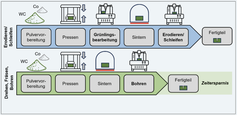
In the non-conventional manufacturing route, after powder preparation and the first shaping process (pressing), the second shaping process is performed on the green body. This is followed by sintering and the machining of the final geometry. Both the green body machining and the final machining step often involve long production times. Machining of sintered carbide with geometrically defined cutting edges, which would eliminate both the green body machining and time-intensive processes such as electrical discharge machining (EDM) or grinding, has not been possible until now due to technological limitations [4]. By substituting non-conventional processes like EDM with more time-efficient drilling operations, there is significant potential for reducing production time. However, this requires the use of high-performance tools whose cutting edges can withstand the stresses that occur during the machining of sintered carbide [1].
Through a specific selection of the carbide substrate regarding grain size and binder content [5], combined with diamond coatings applied to the carbide substrate, it is ensured that the penetrating cutting edge has a higher hardness than the carbide workpiece [6]. Particularly, chemically vapor-deposited (CVD) diamond coating systems are a powerful means to significantly increase the wear resistance of cutting tools due to their nowadays customizable specifications [7]. The prerequisite is that the substrate is also designed for the load collective. Here, sufficient support effect and good coating adhesion are of central importance [6]. The mechanical properties of the carbide substrate depend mainly on the grain size and binder content. A reduction in the average WC grain size increases both wear resistance and hardness as well as compressive and transverse rupture strength. Thus, by using finer WC grains, improved cutting edge stability can be achieved when using sharp cutting edges, such as in micro-drilling tools. The Co binder content, on the other hand, is crucial for the toughness of the carbide, which increases with higher Co content [8].
Studies have already been conducted to qualify cutting tools with geometrically defined cutting edges for machining sintered carbide [3]. Bergs et al. focused on milling sintered carbide (1,200 HV10). They concluded that using a nanocrystalline substrate with improved hardness and toughness compared to conventional carbide significantly increased the feasibility of machining. Both TiAlN and Al2O3 coating systems were most promising due to their high hardness and good adhesion properties. Additionally, further studies aim to modify the micro-geometry of the tools [9]. Doetz examined ultraprecision machining of carbide with single-crystal diamond tools. Turning investigations showed that the choice of coolant significantly impacts tool life [10]. Besides the application-specific design of the substrate, coating, and micro-geometry, there is potential through a modified process strategy. Brehl et al. summarized that using 1D and 2D vibration-assisted machining significantly reduced process forces when turning sintered carbide compared to continuous feed motion. Their investigations also showed that the longest tool life was achieved, especially with diamond-coated tools [11].
So far, most of the conducted work has focused on realizing carbide machining through turning or milling processes. However, drilling of carbide remains largely unexplored. This paper, therefore, presents the potential of drilling sintered carbide of the application group ISO G50. Using a tool concept consisting of an ultrafine-grained carbide substrate combined with a CVD diamond coating and a specific design of cutting parameters, the Institute of Machining Technology (ISF) at TU Dortmund was able to increase the drilling distance from l < 20mm at the beginning of the study to l = 580mm.
Experimental Conditions
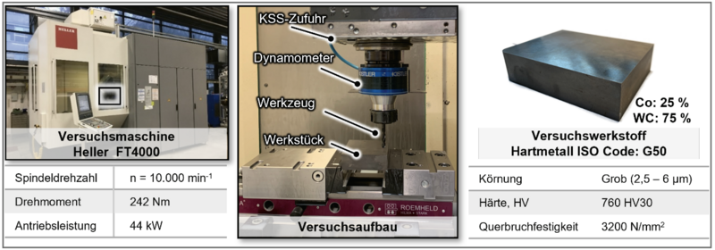
The drilling tests were conducted at ISF on a Heller FT4000 drilling-milling center. The machine features a swiveling motor milling spindle and offers both internal and external coolant (KSS) supply. For the test, the workpiece was initially fixed using a center clamp mounted on the work table. The machine, experimental setup, and the carbide workpiece are shown in Figure 2. A Kistler Type 9170 rotating dynamometer was used to measure the process forces, with the tool fixed using a collet. The drilling depth was lt = 20mm. A constant cutting speed of vc = 10m/min, recommended by the tool manufacturer Ceratizit S.A. based on preliminary investigations, was chosen. The feed rate was varied between f = 0.01…0.1mm. An emulsion (Bechem Avantin 4409) was used as the flood coolant. To statistically ensure the test results, a repeat test was performed for each parameter combination.
Test Material
The test material used was a carbide with ISO Code G50 in cubic shape with dimensions (l/w/h 100x80x27mm) from Ceratizit S.A, as shown in Figure 2. This type of carbide, due to its high cobalt content of 25% and coarse grain size (2.5…6µm), exhibits very high toughness and thus relatively low hardness of 760 HV30. Typical applications include dies, deep-drawing and shearing tools, and forming tools.
Test Tools and Tool-Specific Cutting Parameter Design
Two different special tools with a tool diameter of d = 6.4mm, made from various carbide grades, were used for the tests, with their key properties shown in Figure 3. One of the substrates used was a carbide grade K05-K10, which has a cobalt content of 6% and a grain size of 0.5…0.8µm (ultrafine grain).
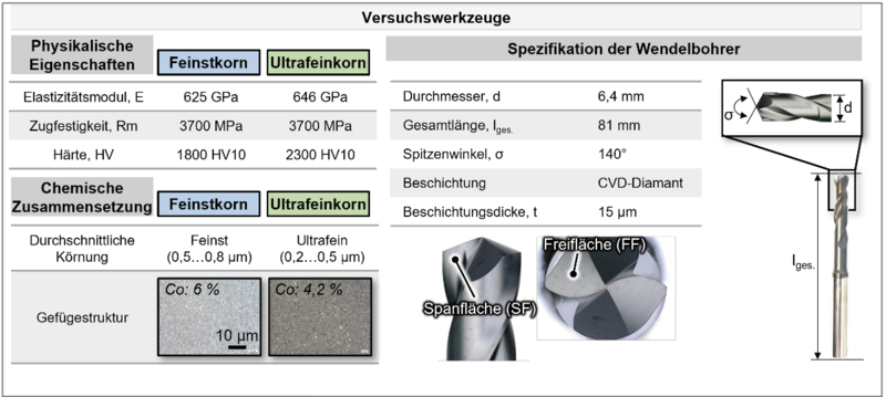
Additionally, a carbide grade K10, with a cobalt content of 4.2% and a grain size of 0.2…0.5µm (ultrafine grain), was used. Both tool types were coated with a multilayer CVD (Chemical Vapor Deposition) diamond coating with a layer thickness of t = 15µm. The multilayer structure, combined with a nanocrystalline microstructure, aims to significantly reduce crack formation at the coating interface, preventing premature coating failure. The measured coating hardness is 10,000 HV0.05 [7]. The cutting edge radius of the tools was measured using a strip light microscope from LMI, averaging rβ = 22µm across both tools. Further specifications, particularly regarding the tool's macro geometry, can be found in Figure 3.
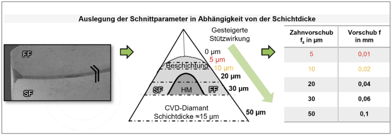
The design of the parameter range for the feed rate was based on the applied thickness of the diamond coating. As shown in Figure 4, a successive increase in the tooth feed starting from 5µm (below the coating thickness) up to 50µm (above the coating thickness) was chosen. This allowed for different support effects from the substrate to be set, enabling a systematic investigation of its relevance for the machining of the carbide.
Results - Great Potential through the Use of Ultrafine Grain Carbide
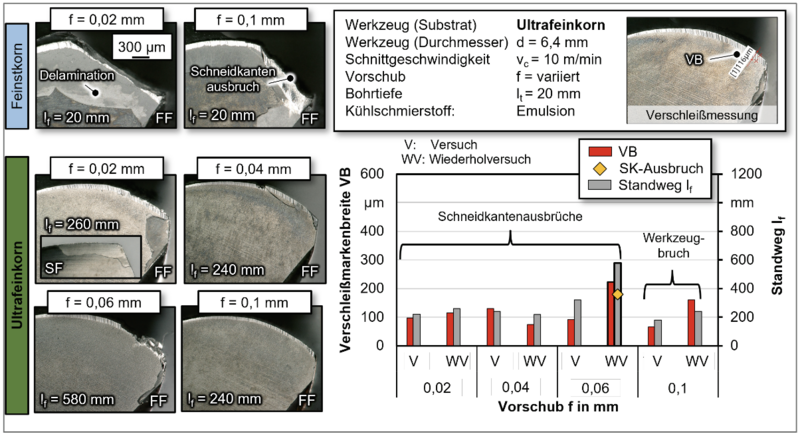
The following presents the results of the tool life study, which aims to demonstrate the feasibility of carbide drilling with diamond-coated carbide tools. The focus is on the variation of the tool substrate and the feed rate. Tool wear, as a crucial evaluation criterion, was analyzed both qualitatively and quantitatively using reflected light microscope images. The initial investigations were conducted with the fine-grained carbide tool. Regardless of the chosen feed rate, each tool exhibited significant cutting edge chipping and large-scale delamination of the coating. Figure 5 (top left) illustrates the tool wear condition at two different feed rates, f = 0.02mm and f = 0.1mm, after a single drilling operation.
The subsequent tests involved the use of ultrafine-grained carbide tooling. A significant increase in tool life can be observed, ranging between lf = 240…580mm depending on the feed rate. At the two lowest feed rates, the tool life remains relatively similar and then significantly increases at f = 0.06mm. This can be attributed to the increased support effect, which counters shear forces, thus positively affecting tool life. However, at a feed rate of f = 0.06mm, the overall highest tool life is achieved. A further increase to f = 0.1mm resulted in a sudden tool breakage after a tool life of lf = 180 and 240mm. Tool life was terminated due to catastrophic edge chipping or tool breakage, which can be attributed to the wear-induced increase in process forces.
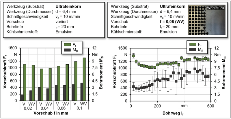
In Figure 6, the left side illustrates the average mechanical tool loads for different feed rates. It is evident that at a feed rate of f = 0.02mm, the values for feed force are comparable to those at f = 0.06mm. Hence, it can be assumed that not only the reduced support effect of the substrate for the coating but also the higher area-specific loads contributed to premature tool failure at the lowest feed rate. Both load components increase with increasing feed rate from f = 0.04mm onwards. At f = 0.1mm, these values exceed critical thresholds, leading to the aforementioned tool breakages. On the right side of Figure 6, the process forces are plotted as a function of drilling depth for a feed rate of f = 0.06mm. Particularly, the feed force exhibits a regressive trend up to a drilling depth of lf = 200mm, attributed to the tool edge's run-in behavior. Subsequently, the feed force increases proportionally until it reaches an approximately constant level of Ff = 1,100N.
The initial drilling torque MB is MB = 3Nm and shows a progressive trend with low standard deviation. As wear progresses, the standard deviation increases, and the drilling torque stabilizes at a mean value of MB = 6Nm. Considering the wear (see Fig. 5), it is suspected that both the maximum drilling torques of MB > 9Nm and the high-frequency dynamic excitation of the tool led to sudden failures.
Summary
The presented investigations demonstrate significant potential for carbide tooling with defined cutting edges. Through a specific design of a special drilling tool regarding the carbide tooling, the application of a CVD diamond coating, and an experimental feed design, a maximum drilling depth of lf = 580mm was achieved in sintered carbide G50. The use of ultrafine-grained carbide proved advantageous over fine-grained carbide. With consideration to the coating thickness and the acting feed forces, the greatest tool life was achieved with a cutting speed of vc = 10m/min and a feed rate of f = 0.06mm. Although the results are promising, drilling sintered carbide remains a significant challenge. For further advancement of knowledge, future studies should include a variation of cutting parameters, including feed rates, as well as an examination of the influence of cutting fluid, which was not specifically tailored to carbide machining in this study. Moreover, further investigations into the substrate influence are conceivable, with particular emphasis on increased tungsten carbide content. Additionally, the coating significantly affects tool wear development, and its specification, particularly the layer thickness, is closely correlated with the chosen feed rate and requires further investigation. Finally, the influence of tool micro- and macrogeometry on carbide machining should be explored in future studies.