Minimal-volume lubrication in vibration-assisted drilling – rethinking efficiency
Drilling is one of the most widely used machining processes worldwide. The process places high demands on the tool, the machine and process control. This is due to the typical process kinematics, in which the tool continuously penetrates the workpiece whilst the resulting chips must be removed from the bore via the flutes. Chip removal becomes particularly difficult as the drilling depth increases, with noticeable consequences for process stability and component quality. The restricted chip removal during drilling leads to increasing friction between the tool, the chips and the bore wall. In practice, this manifests itself as continuously rising temperatures in the contact zone as the drilling depth increases – a thermally stable state is generally not achieved. This is particularly critical in the case of materials that produce long chips, ductile materials or those that are difficult to machine. Here, friction and heat input are further exacerbated, which can lead to negative consequences in terms of dimensional accuracy, surface quality and tool life. In extreme cases, thermally induced changes in the peripheral zones of the component cannot be ruled out.
Vibration-assisted drilling offers a promising approach to overcoming these challenges (Fig. 1). Unlike conventional drilling, this method superimposes a targeted, low-frequency, periodic oscillation onto the continuous feed motion. The tool temporarily exits and re-enters the workpiece. This kinematic interruption of chip formation results in short, well-defined chips, thereby enabling significantly easier chip removal than with conventional drilling. In industrial practice, this means lower chip friction and consequently reduced heat generation during the process. The process demonstrates its advantages over conventional drilling particularly with demanding materials such as titanium or nickel-based alloys, and also at greater drilling depths, as the lower temperature build-up results in fewer process interruptions and higher borehole quality. An additional advantage of vibration-assisted drilling lies in the improved ability to supply coolant. Due to the periodic tool exit, the chip formation zone can be repeatedly supplied with coolant, which is difficult to achieve with conventional drilling. This opens up significant potential for optimised lubrication strategies in vibration-assisted drilling.
In addition to conventional flood lubrication, minimum quantity lubrication (MQL) is of particular interest due to its lower resource consumption and the elimination of coolant maintenance measures. In MQL, small quantities of coolant are finely atomised using an air stream and transported directly into the contact zone. The required coolant flow rate can thus be significantly reduced, from several litres per minute in flood lubrication to just a few millilitres per hour in MMS. This allows resources to be saved, costs to be reduced and the environmental footprint of production to be significantly lowered. In applied research, however, the influence of MMS on chip formation is not uniformly agreed upon. Whilst some studies report increased thermal loads, others demonstrate clear advantages such as lower cutting forces, reduced tool wear and improved surface quality. One reason for these differing results is very likely the dependence of the coolant’s effect on system-specific parameters of the MMS system, such as the type of feed.
This is precisely where the current project comes in: in a basic research project funded by the German Research Foundation (DFG) as part of Priority Programme 2231 – FluSimPro, the causal relationships and mechanisms between vibration-assisted drilling and minimum quantity lubrication are being specifically investigated in order to identify potential for improvement in industrial applications. The guiding principle of the research is based on the realisation that the method of MMS supply and the quantitative dependence of the physically relevant variables for the chip formation process on the system and control variables of the MMS supply are decisive. This should enable comparable and transferable conclusions to be drawn regarding the effectiveness of MMS. In the long term, the aim is to further increase the efficiency of MMS. For users, this would mean not only technological advantages but also a concrete contribution to greater sustainability in manufacturing.
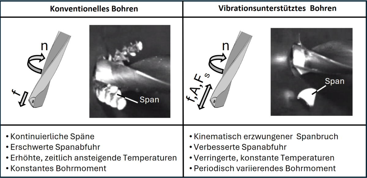
Fig. 1: Comparison of conventional and vibration-assisted drilling.
Overview of the experimental setup and minimum quantity lubrication
The experimental investigations were carried out on a modified machining centre equipped with a LeviSpin tool spindle with active magnetic bearings from KEBA GmbH, which enables both conventional drilling and vibration-assisted drilling. The tool is clamped using a quick-change system with an HSK-32 interface (Fig. 2).
The minimum quantity lubrication was supplied via the Breeze LSJ30 single-channel system from HPM Technologie GmbH. In this system, the air-coolant mixture is generated in an external pressure vessel. A characteristic feature of single-channel systems is that both the liquid coolant and the air-coolant mixture (aerosol) are contained within the same pressure vessel. The coolant is drawn in from the lower part of the pressure vessel via a Venturi nozzle and finely atomised by the air flow within the nozzle. The resulting aerosol is then returned to the upper pressure vessel. From here, it is continuously conveyed via the rotary union of the tool spindle, the tool holder and the cooling channels integrated into the tool, directly into the contact zone.
In the single-channel system used, the MMS is adjusted via three system-specific control variables:
- p1: Inlet pressure at the Venturi nozzle
- p2: Pressure at the pressure relief valve upstream of the pressure vessel
- afl: Level of the cooling lubricant in the pressure vessel
The cooling lubricant used was the synthetic oil Alumicut 659 (Setral Chemie GmbH), which has a density of 0.8975 g/cm³ at 20 °C. For stable operation of the MMS system, the condition (p1 − p2) ≥ 1 bar must be met. If this pressure difference is not present, there is insufficient pressure difference between the Venturi nozzle and the pressure vessel, meaning that no aerosol can be generated.
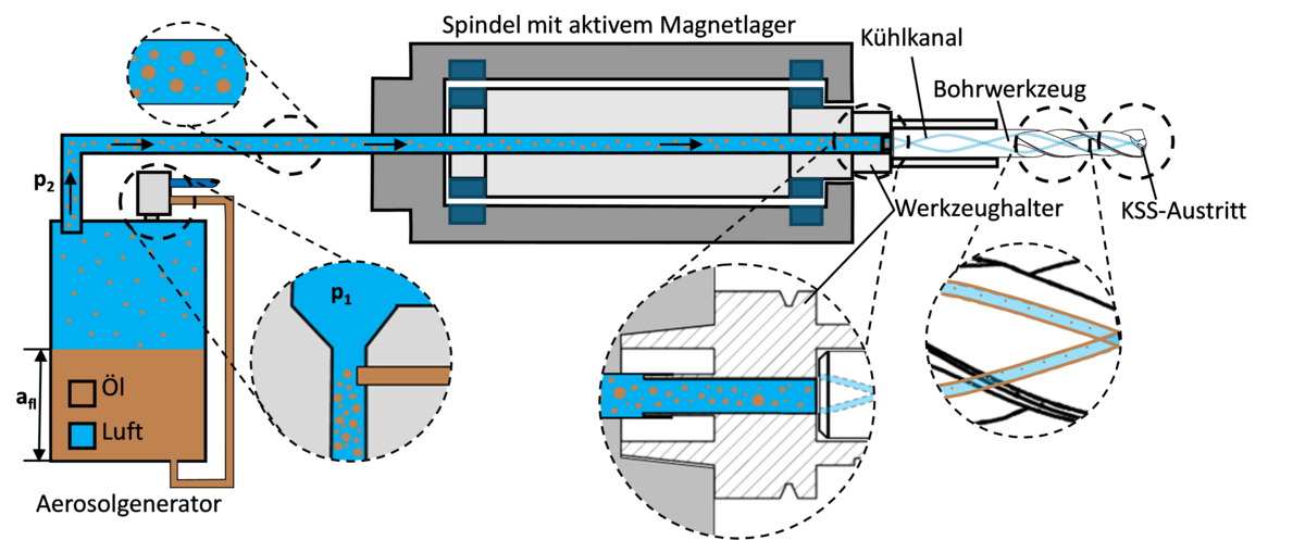
Fig. 2: Schematic diagram of aerosol generation and delivery during vibration-assisted drilling, adapted from [1]
Comparability through fluid dynamics parameters
To achieve results that are comparable across systems, fluid dynamics parameters were derived from the system-specific control variables. The oil mass flow rate was determined gravimetrically by measuring the volume of oil delivered over a period of 30 minutes. The air mass flow was calculated from the volume flow measured at the outlet of the internal cooling channels and the applied/set pressure (Fig. 3).
An investigation into the influence of the system-specific control variables p1, p2 and afl on the air and oil mass flows reveals that, due to the sharp reduction in cross-sectional area, flow velocities of up to approximately 340 m/s (close to the speed of sound) occur in the Venturi nozzle. In this state, the pressure adjustable within the system is largely determined by the nozzle geometry and the inlet pressure p1 and is transmitted directly to the pressure vessel. Changes to the downstream pressure level p2 below this critical pressure have no effect on the resulting air and oil mass flows, which is of central importance for the stable operation of the system. However, if p2 exceeds the critical pressure pcr = 0.76·p1, the air mass flow increases as p2 rises, whilst the oil mass flow decreases accordingly. If the pressure ratio p2/p1 = 0.76 is kept constant, an increase in p1 leads to a linear increase in both the air and oil mass flows.
In addition to the pressure levels, the oil level afl also influences the oil mass flow. This is due to the varying distance between the Venturi nozzle and the liquid surface in the tank. Whilst the air mass flow remains independent of the fill level for a given inlet pressure p1, the oil mass flow decreases linearly as the fill level rises. For example, at p1 = 8 bar and p2 = 1 bar, the oil mass flow rate drops from 13.2 mg/s at a fill level of 80 mm to 1.7 mg/s at 150 mm. This effect is even more pronounced at higher inlet pressures.
Fig. 3 summarises the influence of the parameters p1, p2 and afl on the air and oil mass flows at the outlet of the internal cooling channels. Further combinations of control variables for the MMS system are the subject of ongoing investigations. Based on these observations, process-specific parameters can now be determined (tool wear, drilling torque, feed force, process temperature).
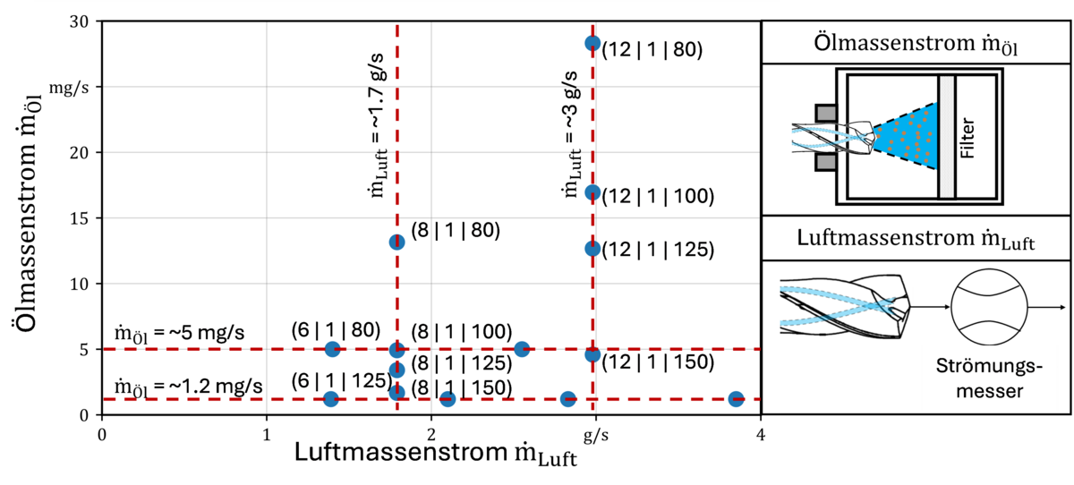
Fig. 3: Dependence of the oil and air mass flow rates at the outlet of the internal cooling channels on the control variables (p1 in bar | p2 in bar | afl in mm)
Visualisation of the proportion of oil delivered to the chip zone
In addition to the quantitative measurement of air and oil mass flows, the flow behaviour of the coolant and the aerosol was also investigated directly at the outlet of the cooling channels integrated into the drilling tool. The aim was to gain a better understanding of the form in which the cooling lubricant actually reaches the contact zone, in order to derive insights for more efficient wetting of the working surfaces. The visualisation of the coolant-air flow emerging from the drilling tool was carried out using the high-speed shadowgraph method. As shown in Figure 4, the outlet area of the cooling channels is positioned between a light source and a high-speed camera. The shadow caused by the emerging coolant is recorded by the camera, enabling an analysis of the flow behaviour. Due to the high flow velocities at the outlet of the cooling channel, a high-speed camera with a frame rate of 140 kHz was used. This high temporal resolution is necessary to reliably capture the dynamic processes occurring during the discharge of the coolant. In addition to the experimental setup, Figure 4 shows exemplary, binarised images from the high-speed camera. It becomes clear that, contrary to intuitive expectations, the coolant does not primarily exit in the form of fine droplets, i.e. as an aerosol, but predominantly as so-called oil ligaments. This suggests that, during transport through the cooling channels, the oil in the generated air-coolant mixture partially deposits on the channel walls and is transported further there as a wall film. These results also confirm the findings of [2]. It is only at the outlet of the cooling channels that this oil film is detached again and fed to the chip zone in the form of ligaments. This periodic detachment process of the oil film at the outlet of the cooling channels is referred to below as an ‘event’. Analysis of the high-speed recordings consistently shows that the event frequency increases with rising air and oil mass flows. A plausible reason for this behaviour lies in the relative velocity between air and oil. As the air velocity increases, the shear stress at the surface of the oil film rises. This amplifies instabilities on the oil film surface, which promotes the detachment of the oil agglomerated at the cooling channel outlet. Consequently, the oil is detached more frequently and undergoes secondary atomisation. These observations thus illustrate that the cooling lubricant does not exit the cooling channels exclusively in the form of droplets as a finely dispersed aerosol, but to a considerable extent in the form of filaments.
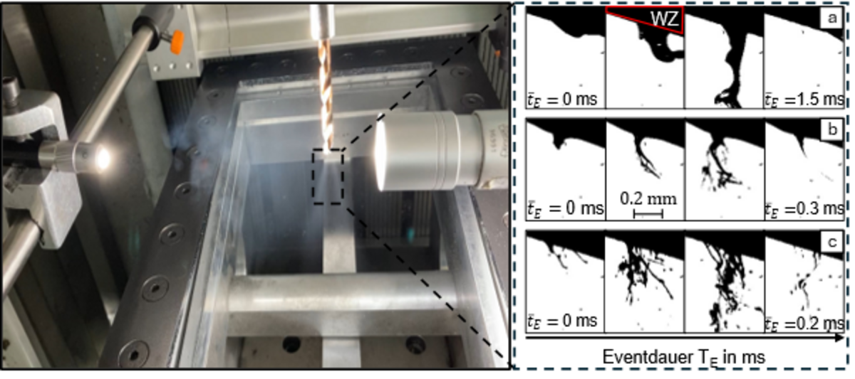
Fig. 4: Experimental setup for the shadow casting method and selected high-speed camera recordings for various system-specific control variables (p1 in bar | p2 in bar | afl in mm) of the MMS system, (a: (6|1|125), b: (8|1|125), c: (12|1|125)), according to [1]
Wetting of the bottom of the bore – a comparison of simulation results
The experimental visualisations of the flow behaviour at the outlet of the cooling channel do not clearly indicate which areas of the bottom of the bore are actually wetted, nor how different supply patterns affect the coolant distribution. Whilst a ribbon-like supply should enable targeted application due to its directed movement, it can be assumed that areas near the edges of the bore bottom are preferentially wetted when the tool is not in engagement. With finely atomised coolant droplets, on the other hand, the hypothesis was that these could also wet more central areas of the bore bottom due to their lower inertia.
To test these hypotheses specifically and to explain the experimental observations in a mechanism-based manner, wetting simulations were carried out. The aim of these simulations was to systematically investigate the influence of the observed supply forms (filament-like and droplet-like) on the distribution of the coolant at the bottom of the borehole and to draw conclusions from this for an optimised MMS design in vibration-assisted drilling. Figure 5 shows the results of the wetting simulations for the described forms of coolant supply at the bottom of the borehole. Three rotational speed levels (0, 600 and 1000 min⁻¹) are shown in each case to also incorporate the influence of tool rotation on coolant distribution. Due to the complexity, chip formation could not be taken into account in the simulations. The left-hand column shows the wetting pattern for a coolant supply consisting predominantly of ligaments. Even when the tool is stationary (0 min⁻¹), it is evident that the coolant tends to strike the peripheral area of the bottom of the bore. As the rotational speed increases, the coolant is transported further outwards by the rotation, so that wetting increasingly concentrates on an annular area near the bore wall. The central area of the bottom of the bore remains largely unwetted. The right-hand column, however, shows the results for a drop-shaped supply. In this case, as expected, the coolant is distributed much more evenly even at low speeds. Due to the lower inertia of the drops, these tend to reach the central area of the bottom of the bore. As the speed increases, the surface wetting continues to increase, with the area around the centre of the bore being reliably reached in particular.
The simulations allow the following important conclusions to be drawn:
- A ligament-like supply promotes increased coolant supply to the peripheral area of the bottom of the bore, particularly near the main cutting edges, which should result in improved lubrication in this area.
- A drop-shaped supply enables effective wetting of the central bottom of the bore, particularly also in the area of the transverse cutting edge. As the mechanical loads on the tool are particularly high here due to friction and squeezing processes, this should have a positive effect through reduced friction.
- None of the supply configurations examined on their own can guarantee complete wetting of the entire bottom of the bore. Only a combination of ligament-like and teardrop-shaped supply has the potential to reliably supply both the peripheral and central areas with coolant, thereby reducing the thermal and mechanical loads on the tool and the workpiece.
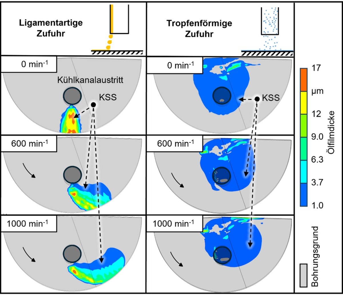
Fig. 5: Wetting simulation for ligament-like and drop-shaped coolant supply and their effect on coolant distribution at the bottom of the borehole, according to [3]
Conclusion and implications for industrial applications
Vibration-assisted drilling is particularly well suited to demanding machining tasks, such as the machining of ductile, difficult-to-machine materials and/or drilling operations with high length-to-diameter ratios. The superimposition of the linear feed motion with the vibrational motion results in periodically increasing and decreasing drilling torques, which lead to increased mechanical stress on the tool at the maximum chip thickness. The thermal load is reduced compared to conventional drilling due to the interrupted cut and the resulting improved chip removal.
The kinematically induced interruption of chip formation also opens up possibilities for improved supply of coolant to the cutting zone under MMS conditions, which is being systematically investigated in a collaborative project between the Leibniz Institute for Material-Oriented Technologies (IWT) and the University of Bremen. The basis for this is the mapping of specific control variables of the MMS system onto the physically effective variables, which in this case are the mass flows of air and coolant. This demonstrated that, under the given machining conditions, there is a significant difference in the measured machining temperatures between dry machining and machining with the MMS system switched on. In contrast, varying the oil mass flow rate at a constant air flow rate had no discernible effect on the temperature. An increase in the air mass flow rate at a constant oil mass flow rate led to a demonstrable drop in temperature due to improved convective cooling.
Furthermore, it was demonstrated that the coolant emerges from the cooling channels predominantly as liquid filaments rather than as an aerosol. Simulation calculations also show that filament-like and droplet-shaped supply wet different areas of the bottom of the borehole to varying degrees. A balanced combination of both supply types would enable extensive MFL supply to the bottom of the borehole, thereby creating the conditions for reduced friction, lower thermal loads and greater process stability. Building on this, an increase in the aerosol fraction at the outlet of the internal cooling channels should be aimed for. In general terms, this means designing the minimum quantity lubrication specifically to achieve a coolant supply to the bottom of the borehole that is tailored to the machining task and meets the actual demand. This would allow tool life, productivity and the quality of the machining result in vibratory drilling to be increased without having to significantly increase resource consumption.
Outlook: Predictive optimisation through the coupling of flow and chip formation simulation
For the predictive optimisation of the vibratory drilling process, the findings from experimental investigations into the coupling of chip formation simulation with flow simulation are utilised. In an initial approach, heat transfer and friction coefficients experimentally determined on surfaces wetted with coolant serve as coupling parameters. Furthermore, friction coefficient distributions depending on coolant volume, supply form and degree of wetting can then be incorporated into chip formation simulations based on the results of wetting simulations. This would allow local statements regarding cutting forces, temperature development and, consequently, tool loading and chip shape to be made with significantly greater precision than previously. In the long term, this offers the possibility of realising digital process models with which the control variables of the MMS system, the tool geometry and the control variables of the vibratory drilling process can be specifically coordinated.
Funding note:
Funded by the German Research Foundation (DFG) – Project number: 439950037
Sources:
[1] Schumski, L., Tonn, T., Sölter, J., Avila, K., Buss, L., Karpuschewski, B., Fritsching, U., 2024, Minimum Quantity Lubrication (MQL) Supply through Internal Cooling Channels in Drilling Processes, Journal of Manufacturing and Materials Processing, 8(2). doi.org/10.3390/jmmp8020069
[2] Stampfer, B., Zanger, F., Schulze, V., 2019, In-Process Analysis of Minimum Quantity Lubrication during Drilling of AISI 4140, in Advances in Production Research, Springer Nature: Switzerland, pp. 541–550. doi.org/10.1007/978-3-030-03451-1_53
[3] Tonn, T., Geppert, A., Schumski, L., Buss, L., Sölter, J., Karpuschewski, B., Fritsching, U., 2026, Distribution of metalworking fluid in vibration-assisted drilling using minimum quantity lubrication, Production Engineering, 20(1). doi.org/10.1007/s11740-025-01388-1