Modelling the cooling effect in tool grinding - under consideration of process-related uncertainties
__Benjamin Bergmann, Klaas Maximilian Heide, Berend Denkena, Frederik Wiesener
Flute grinding is a central step in the machining process for the production of geometrically defined cutting tools, such as end mills or drills. A large proportion of the mechanical energy introduced during this process is converted into heat. Depending on the cutting conditions, up to 95 % of the energy is transferred into the workpiece [1]. The remaining energy is distributed between the tool, the chips and the cooling lubricant. The heat flow into the workpiece is particularly critical, as this can lead to grinding burn and thermally induced residual stresses. This reduces the usability, surface quality and dimensional accuracy of the workpiece [1]. Due to the large number of individual grain interventions, the grinding process represents a complex engagement situation. Despite constant process parameters, significant differences in process forces, contact zone temperatures and resulting surfaces can be observed [2]. This is partly due to stochastic effects in the grinding contact zone [3]. Wear mechanisms, such as bond clogging, grain chipping and grain flattening, significantly influence the grinding wheel microtopography and thus the contact between grinding wheel and workpiece [4]. The effectiveness of the cooling effect of the cooling lubricant is significantly influenced by these factors [5]. In practice, the adjustment of cooling lubricant nozzles and the selection of the appropriate grinding fluid are often made on the basis of experience-based knowledge or time-consuming adjustment trials. Simulations, on the other hand, offer a cost-effective alternative for predicting the mentioned effects and ensuring optimum process settings. In particular, novel approaches to multiscale simulations can predict the interaction of microscopic and macroscopic phenomena in a short computing time [6]. Stochastic effects caused by individual grain interventions are taken into account, which allows the grinding process to be analysed in detail.
Multiscale simulation Approach
In cooperation with the Centre for Industrial Mathematics at the University of Bremen, the Institute of Production Engineering and Machine Tools at Leibniz Universität Hannover is researching on multiscale material removal and thermo-fluid-dynamic simulations for tool grinding. A particular aspect in this regard is the ‘fuzzy’ consideration of the cooling lubricant distribution and the resulting thermal workpiece load in the contact zone. In this case, the term ‘multiscale’ means that processes are simulated both at the macro scale (entire workpiece and grinding wheels) and at the micro scale (partial area of the contact zone between grinding wheel and workpiece, including individual abrasive grains). Furthermore, different simulation methods are coupled on both levels. The computationally efficient dexel simulation ‘IFW-CutS’ is used to simulate the material removal process. The FE-based simulation application ‘FeatFlow’ is used to calculate the cooling lubricant flow and temperature propagation. The aim is to record the large number of different interactions and their influence on the process result in order to ultimately derive optimisation strategies for the grinding process.
Macrosimulation
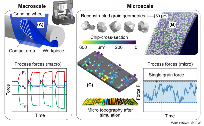
On the macroscopic scale, the entire machine kinematics including the grinding wheel and the workpiece are considered. The components are reduced to simple geometric objects to save computing power and time. In addition to the resulting macroscopic workpiece geometry, the output variables include the material removal rate, total chip-cross-sections, contact surfaces and local engagement widths/depths of the grinding wheel (see Figure 1 A). As the grinding wheel engagement remains constant over the course of the flute after the run-in process has been completed, a sub-region of the contact zone is sufficient for the detailed observation of the process on the microscale.
Microsimulation
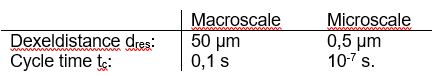
On the microscopic scale, the process is locally simulated with individual abrasive grains. Here, the analysis concentrates on the contact zone between the workpiece and the grinding wheel, but with a significantly higher geometric resolution and very short simulation cycle times (see Table 1). The grinding wheel surface is digitally simulated using a parametric grinding wheel model, in which individual abrasive grains are taken into account [7] (see Figure 1 B). For this purpose, diamond grains from L.M. Van Moppes & Sons SA (FMD series) were optically captured using focus variation on an Alicona infinite Focus G5 and 3D models of individual grains were reconstructed from the scan data. The stochastic distribution of abrasive grains along the grinding wheel circumference is based on the volumetric composition of the grinding wheel. The required number of grains is calculated by specifying the grinding wheel diameter, width, grain size and concentration. The dressing process is simulated by resetting the grinding wheel bond in order to set different micro topographies and the resulting sharpening states of the grinding wheel. Assuming that up to 20 % of the grain can protrude from the bond due to the limited grain retention force of the bond [8], the combination of bond reset and an adjustable maximum grain protrusion allows variable grinding wheel micro topographies to be achieved. Time-consuming topography scans are not required. To parameterise and validate the developed model, real grinding wheel surfaces were analysed at different wear states and compared with the digitally generated grinding wheel surfaces. Furthermore, resulting workpiece surfaces from surface grinding experiments were compared with corresponding microsimulation results and the prediction quality of the grinding wheel model was evaluated using roughness parameters. Figure 1 C, below, shows an example of the simulated microtopography of the workpiece with a grain size of D54.
The microsimulation enables the calculation of engagement conditions for each individual abrasive grain. Depending on the use case, more than 100,000 individual grains are modelled and engagement depths, widths, individual grain chip-cross-sections and cutting volumes are calculated (see Figure 1 C). Cutting forces and cutting power are predicted by applying an empirical single grain force model (see single grain force modelling). Due to the large number of different grains, stochastic effects caused by varying grain protrusions and orientations can be taken into account. Wear mechanisms such as grain breakouts, flattening and bond clogging as well as brittle material cutting behaviour can optionally be included in the simulation. As all active cutting grains have passed the contact zone after one complete revolution of the grinding wheel, only a few rotations are required to obtain valid results. In addition to technological parameters such as contact depths and process forces, the resulting microtopography of the workpiece is available, which is used in the thermo-fluid-dynamic simulation to calculate the cooling lubricant flow. Finally, all results can be transferred to the macroscale by normalising the macroscopic contact conditions over the entire contact zone and then applying this normalized engagement field to the results from the microsimulation. As mentioned previously, the single grain forces and cutting power are calculated using an empirical force model.
Single Grain Force Model
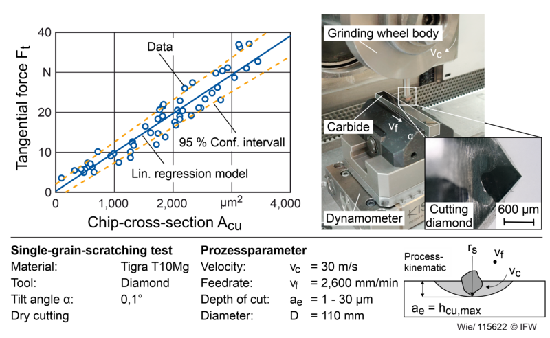
The tangential and normal forces can be calculated using an empirical model on the basis of the single grain chip-cross-section calculated in the microsimulation. Taking the cutting speed into account, the resulting heat output can be determined for each grain. The forces acting over the entire grinding wheel engagement can be calculated as a function of time by integrating over all cutting grains. In order to determine the model coefficients, single grain scratch experiments were carried out at the IFW and the process forces were measured (see Figure 2). An FS 840 KT CNC surface grinding machine from Geibel and Hotz was used for the investigations. A modified grinding wheel is used, consisting of a steel cylinder and a metal round shaft with the scratch diamond. Polished carbide rods from TIGRA GmbH are used as the workpiece. The process forces are measured with a Kistler 9119AA2 dynamometer. For model parameterisation, the grinding forces are evaluated at the point of maximum grain engagement. The carbide sample is tilted slightly to enable the maximum chip thickness in the feed direction to be varied using a suitable combination of cutting and feed speed. The resulting scratch geometries were then analysed using optical surface measurement (Nanofocus µScan). The resulting maximum single grain chip-cross-sections as well as penetration depths and widths were determined. An empirical model was derived by correlating the individual grain chip-cross-sections with the measured process forces. More than 2,000 scratches were analysed to parameterise the model. With an average R2 = 0.96, the linear regression provides sufficiently accurate results for the prediction of tangential and normal forces and for the calculation of the single-grain cutting performance [9].
Cooling lubricant flow and temperature calculation
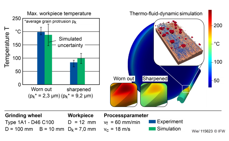
To predict the cooling effect and temperature distribution, the micro topographies and heat flows from the material removal simulation are transferred to the finite element simulation. First, the coolant flow in the grinding gap is simulated locally on the microscale. The microtopography of the grinding wheel and the resulting workpiece surfaces are used for this purpose. Using models for surface wetting behaviour [10], coolant velocities and volume flows, the distribution of the coolant within the contact zone can be modelled locally. As before, these results are scaled to the macroscale. The rough surfaces of the grinding wheel and workpiece, including wetting properties, are effectively described using mathematical models, which are extended to the entire contact zone [11]. The effect of individual grains in conjunction with the grinding wheel bonding material can be considered in this way without having to model these geometrically in the macro simulation. This significantly reduces the calculation time. The finite element simulations can be used to calculate temperature distributions for different cooling conditions and grinding wheel wear states, considering the heat input and heat distribution on the grinding wheel, workpiece, coolant and chips. Figure 3 shows the comparison between experimental investigations and corresponding simulation results. Both in the experiment and in the simulation, the wear state of the grinding wheel was characterised by different grain protrusions. Decreasing grain protrusion leads to increased friction and reduced lubrication of the surfaces. This leads to a significant increase in temperatures, which is not only evident in the experiment, but also in the simulation.
Conclusion and outlook
The increasing complexity of tool designs, new grinding wheel bonding systems and cooling lubricant compositions is increasing the need for simulation solutions for the configuration and planning of tool grinding processes. The optimisation of cooling lubrication strategies, particularly with regard to sustainability and energy efficiency, represents a major leverage for increasing economic efficiency. The methods and models for multiscale process simulation presented here were developed as part of the DFG Priority Programme 2231 and will be finalised over the next two years. In the third and final funding phase of the project, the focus will be on the application of the system for multiscale process analysis and optimisation. For example, further experimental studies on the coolant flow and thermomechanical load at the contact zone are planned. The grinding wheel model presented will be continuously expanded to dynamically predict the condition of the micro topographies depending on the tool life. In this way, dressing cycles can be planned and an optimum grinding tool selection can be made depending on the application.
Source | IFW Hannover