
Grinding with Oscillating Tool Movement Using PKD
High-performance materials, such as carbon-fiber-reinforced plastics (CFRP), are well established in the aerospace industry. However, due to their heterogeneity, anisotropy, and high abrasiveness, they continue to pose significant challenges for machining. For cost-effective machining, polycrystalline diamond (PCD) is therefore frequently used as an extremely hard cutting material. PCD consists of fine-grained diamond crystals embedded in a metallic cobalt binder matrix. Figure 1 shows a drill bit with a brazed PCD tip and the PCD used. Due to its exceptional hardness, diamond is particularly well-suited for applications with high demands on wear resistance and dimensional accuracy, which is why PCD is widely used in drilling, turning, and milling tools [1]. However, the manufacture and reconditioning of these tools require the grinding of PCD, which is associated with high thermal stress and leads to significant wear on the grinding wheel [2; 3]. This compromises process stability, dimensional accuracy, and the cost-effectiveness of machining.
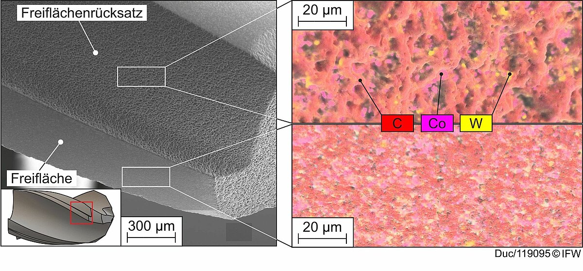
Figure 1: Drill bit used, with a PCD drill tip
In particular, rough grinding of the flutes on PCD drills has so far been considered economically unfeasible. For this reason, electrical discharge machining (EDM) processes are typically used. However, these processes involve long cycle times. In addition, after rough machining by EDM, a subsequent grinding operation is required to achieve the required surface qualities, which necessitates the use of complex hybrid machines and limits industrial applicability. Tool wear during the grinding of PCD results primarily from thermally induced effects, particularly the graphitization of the diamond grains [3]. Ceramically bonded diamond grinding wheels with grain sizes of 15–25 µm are typically used for this process. The ceramic bond offers increased porosity, which improves the supply of coolant to the contact zone and thus reduces the risk of thermal damage. At the same time, the abrasive grains are retained in the bond for a sufficiently long time and are released in a timely manner as wear progresses, ensuring that sharp cutting edges are continuously available [2, 4].
It is known from the grinding of complex components such as turbine blades that a periodic interruption of the grinding contact can lead to a significant reduction in thermal stress [5]. Comparable effects have also been observed in milling with trochoidal feed strategies, in which both the workpiece and the tool could be relieved of thermal stress [6]. For the machining of PCD, the influence of the dynamic process parameters amplitude a and amplitude frequency fdyn has not yet been sufficiently investigated. The aim of this work is therefore to investigate the influence of dynamic process kinematics on the wear behavior of ceramic-bonded diamond grinding wheels during the grinding of PCD. To this end, the investigation was conducted in two steps. First, the influence of the main process parameters—cutting speed vc, feed rate aₑ, and abrasive grain size—was systematically investigated and comparatively evaluated using the G-ratio. Subsequently, the specific influence of dynamic parameters on wear behavior was quantified using wear volume analysis.
Materials and Methods
First, the influence of the process parameters cutting speed vc and depth of cut ae under continuous machining was systematically investigated. The goal was to derive a robust process window and thus establish a reliable reference basis for the subsequent investigations involving periodically interrupted machining. This reference ensures comparability and makes it possible to unambiguously attribute effects to the changed kinematics. To distinguish between roughing and finishing operations, two grain sizes (D15 for finishing and D54 for roughing) were used at a grain concentration of C100. The grinding tests were conducted using ceramic-bonded diamond grinding wheels on a Helitronic Vision 400L (Walter) tool grinding machine. The test setup is shown in Figure 2.
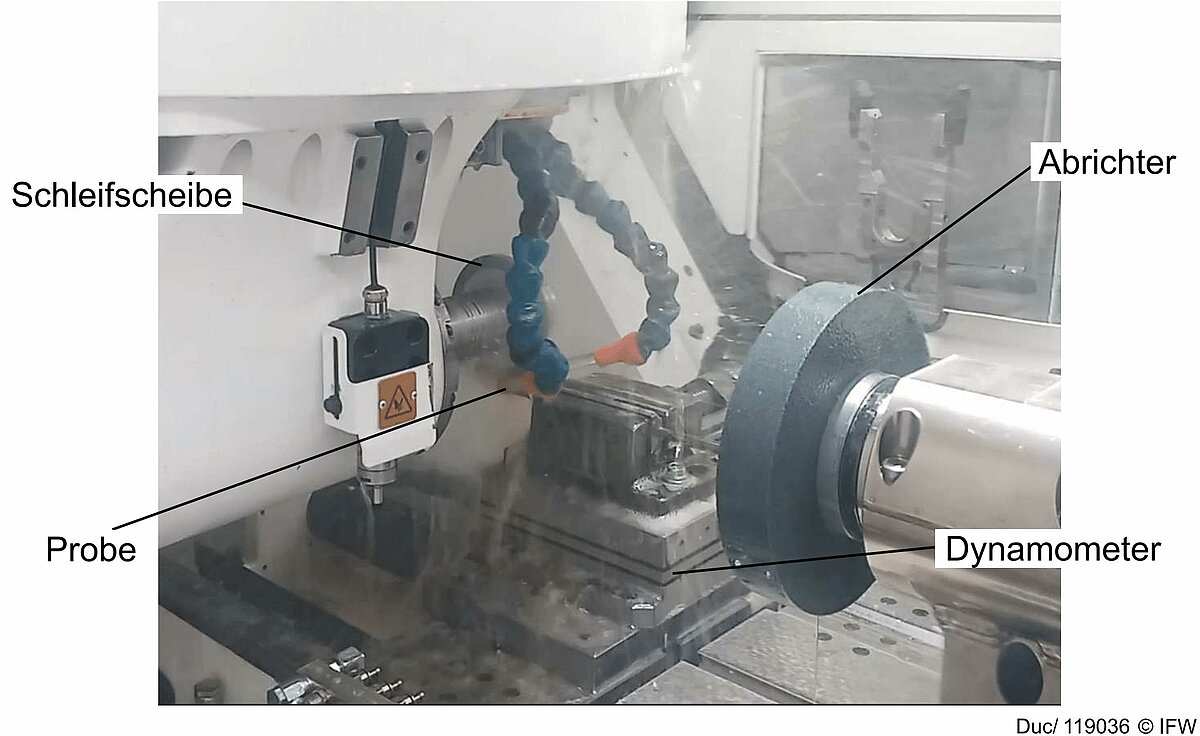
Figure 2: Experimental setup for investigating the process window
The test specimens consisted of carbide drill blanks with a brazed PCD tip (height: 4 mm). The PCD was machined without helical cutting (see Figure 3). With a total depth of cut of ae = 100 µm, the grinding wheel runout is 3.16 mm, corresponding to 79% of the PCD height. To maximize material removal from the PCD, the groove length was set to 4 mm. The grinding wheel runout is thus within the carbide area, outside the PCD.
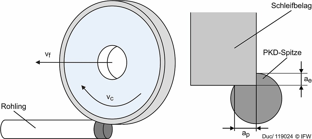
Figure 3: Experimental kinematics and engagement conditions
Table 1 summarizes the range of parameters investigated. To ensure comparability, the total depth of cut was kept constant by varying the number of grinding strokes. At the same time, this approach ensures a sufficient volume of tool wear for the analysis. Due to the selected path strategy, the engagement width ap increases with each stroke. In the final stroke, a maximum engagement width of ap,max = 0.78 mm was achieved. The tool wear volume Vs was determined using the µ-Scan (NanoFocus), and the removed workpiece volume Vw was measured using an Alicona InfiniteFocus G5. The G-ratio was calculated from the ratio G = Vw / Vs.
| Lower Process Window | Top Process Window | |
| Cutting speed vc | 10m/s | 20m/s |
| Delivery ae | 6µm | 12µm |
In the second step of the investigation, the focus was on the influence of the dynamic process parameters amplitude a and amplitude frequency fdyn on tool wear. To this end, a sinusoidal superposition was applied to the grinding kinematics. The amplitude a ranged from 20 to 80 µm, and the frequency fdyn ranged from 5 to 15 Hz (see Table 2).
| Lower Test Window | Top Test Window | |
| Amplitude a | 20μm | 80μm |
| Amplitude frequency fdyn | 5Hz | 15Hz |
The choice of parameters ensures that the amplitude a is at least one-third of the average grain diameter and that the frequencies can be reproducibly achieved within the machine's dynamic limits. This results in periodic contact interruptions without compromising process stability (see Figure 4).
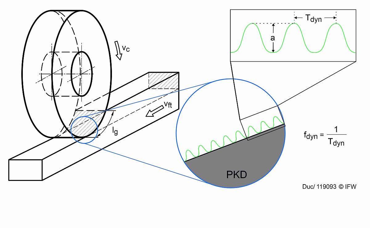
Figure 4: Schematic illustration of grinding with a superimposed pendulum motion
To ensure sufficient statistical validity, each of the four test conditions was repeated three times. To simulate an industrial regrinding process, a pre-eroded drill bit was used, allowing for the machining of a complex groove geometry and a heterogeneous material composite consisting of cemented carbide, PCD, and solder in the experiments. As a result, it was not possible to precisely determine the removed volume and the G-ratio. The experiments were conducted on a Multigrind CU from Haas Schleifmaschinen GmbH (see Figure 5).
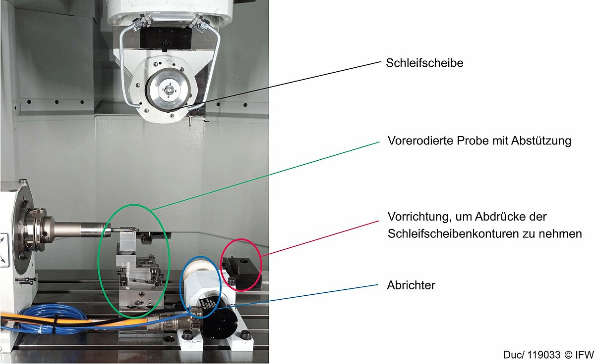
Figure 5: Experimental setup for experiments involving superimposed pendulum motion
Grinding wheel wear was determined by tracing the profile contour onto a graphite plate. Each groove was ground with eleven passes, each with ae = 9 µm, corresponding to a total depth of cut of 99 µm. The mass of the sample was measured before and after machining using a precision scale. To ensure defined initial conditions, the grinding wheel was dressed anew before each groove machining operation.
Results and Discussion of the Preliminary Experiments
Figure 6 shows the G-ratios determined from the roughing tests with D54 grit. At cutting speeds of 10 and 15 m/s, the G-ratio increases with increasing cutting depth. At a cutting speed of 20 m/s, a different behavior is observed. The G-ratio initially remains nearly constant and then decreases as the cutting depth increases. This is caused by the rising thermal load resulting from the higher cutting speed and the contact length, which increases with cutting depth. If the specific energy input exceeds a critical value, the process becomes unstable and the G-ratio decreases. The figure also shows the resulting surface roughness. In the range studied, it decreases with increasing cutting depth, contrary to typical trends seen, for example, in the grinding of cemented carbide. One possible explanation is the increased thermal effect due to the extended contact length, which promotes thermal damage to the PCD surface and rounds off micro-edges in the workpiece. This results in the surface becoming increasingly smoothed.
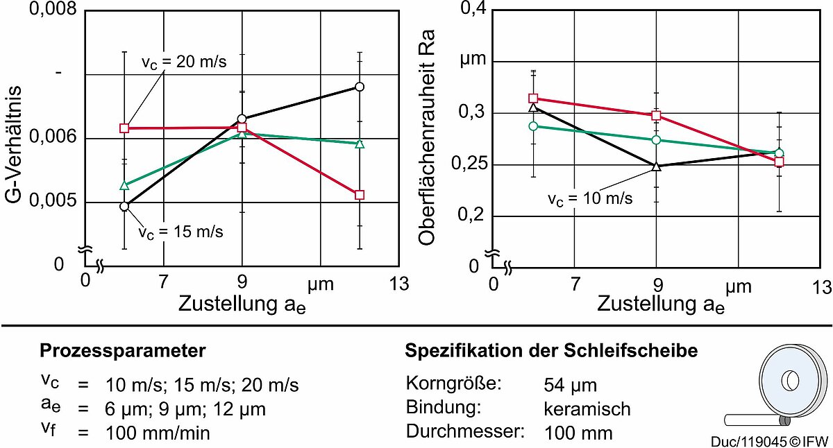
Figure 6: Effect of feed rate and cutting speed on the surface finish and wear during roughing
The G-ratios determined from the finishing tests are summarized in Figure 7. For this purpose, the test points were re-machined using a D15 grinding wheel.
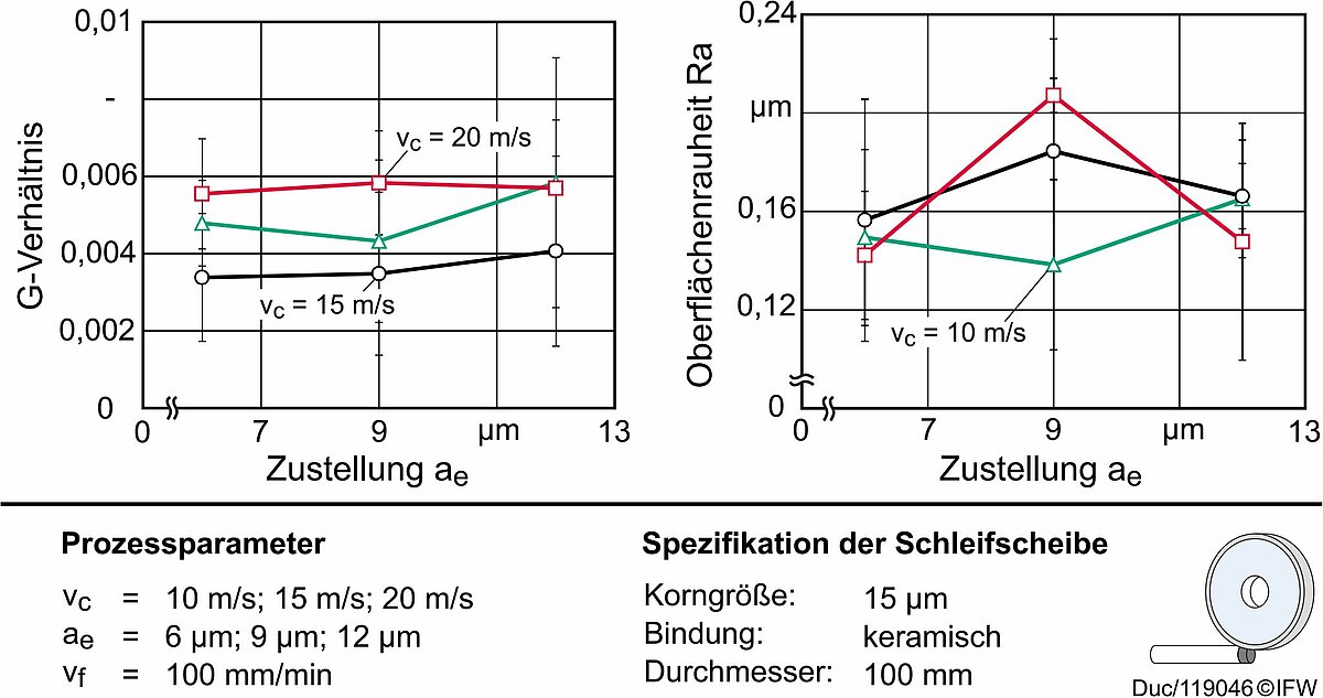
Figure 7: Effect of feed rate and cutting speed on the surface finish and wear during finishing
It can be seen that the G-ratio remains largely constant across the feed range examined and increases with rising cutting speed, from 0.0034 at vc = 15 m/s to 0.0058 at vc = 20 m/s. The G-ratios determined in the finishing tests are lower than those from the roughing tests. This suggests that, within the parameter window under consideration, the coarser grain size D54 exhibits more favorable wear behavior compared to D15. As in the roughing tests, surface roughness was measured. The results shown in Figure 7 do not reveal any clear influence of the parameters under investigation. The differences fall within the determined standard deviations and should be interpreted as measurement variation. Nevertheless, lower roughness values were achieved in the finishing tests due to the smaller grain size. Based on these data, tests with discontinuous contact were conducted. For these follow-up tests, the symmetry point fdyn = 10 Hz and vc = 15 m/s served as the starting point for the investigations involving intermittent contact.
Results and Discussion of the Experiments with Discontinuous Contact
The superimposed kinematics cause a periodic interruption of contact between the grinding wheel and the workpiece. This improves the supply of cooling lubricant to the contact zone and lowers the temperature. The dynamic parameters amplitude a and amplitude frequency fdyn were investigated. The calculated wear volumes are plotted against the amplitude in Figure 8. Both parameters were varied across three levels and combined in a cross-shaped experimental design that intersects at the center. This allowed the entire amplitude spectrum to be examined at fdyn = 10 Hz, enabling an analysis of the influence of amplitude. As the amplitude increases, the wear volume decreases. The sharpest decrease in wear volume V occurs between 20 µm and 50 µm. When the amplitude a is further increased to 80 µm, the additional decrease in wear volume is smaller than in the step from 20 µm to 50 µm. This suggests that the cooling effect is largely exhausted at around 50 µm. The grinding gap is adequately supplied with coolant, the thermal load decreases, and with it, thermally induced wear. Although an even greater amplitude promotes more coolant into the gap, it no longer significantly increases the cooling effect. At a constant amplitude of 50 µm, it becomes apparent that the amplitude frequency also significantly influences the wear volume. A reduction in frequency significantly reduces wear. The reason is the longer pause time, during which the cooling lubricant can penetrate deeper into the contact zone. This improves cooling and reduces wear. Unlike the effect of amplitude, this effect persists across the entire frequency range studied. It follows that the duration of the cooling lubricant’s action in the working gap has a greater influence on the cooling effect than the amplitude.
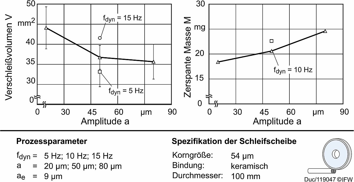
Figure 8: Effect of amplitude a and amplitude frequency fdyn on the wear volume and the machined mass
In order to compare the wear data with the material removal from the test specimens, the mass of the specimens was measured before and after the grinding tests using a scale to determine the mass removed. The results are shown in Figure 8. An inverse trend to the wear volume data can be observed. The observed trend can be attributed solely to the wear volumes generated. With greater wear volume, the additional radial disc wear reduces the effective total depth of cut. Consequently, the removal volumes and thus the mass removed are lower in these tests. The weighing results therefore support the findings of the wear volume analysis.
Summary and Conclusions
The results show that grain size has a significant influence on wear behavior and the G-ratio during PCD grinding. With regard to surface roughness, no clear trend could be identified within the measured range; however, lower average roughness values were achieved during the finishing process. The use of dynamically superimposed grinding kinematics leads to a significant reduction in grinding wheel wear—this is due to improved supply of cooling lubricant to the grinding gap as a result of periodic interruptions in contact and extended exposure times.
Overall, the results illustrate that both the grain size and the parameters of dynamic process control are critical control variables for low-wear process control. However, it appears that adaptive process control, in which amplitude and frequency are dynamically adjusted to the respective machining situation, offers a promising approach for increasing the performance of grinding processes. Future work should investigate the influence of this machining method on dimensional accuracy and component function.
Bibliography
[1] | M’Saoubi, R.; Axinte, D.; Soo, S.L.; Nobel, C.; Attia, H.; Kappmeyer, G.; Engin, S.; Sim, W.-M.: (2015): High performance cutting of advanced aerospace alloys and composite materials. CIRP Annals - Manufacturing Technology, 64, S. 557-580. |
[2] | Kenter, M.: (1990) Schleifen von polykristallinem Diamant. Dr.-Ing. Diss., Universität Bremen. |
[3] | Schindler, F.; Brocker, R.; Klocke, F.; Mattfeld, P.: (2016): A Discussion on Removal Mechanisms in Grinding Polycrystalline Diamond, Journal of Manufacturing Science and Engineering, 138, S. 1449-1452 |
[4] | Friemuth, T. (2002) Herstellung spanender Werkzeuge. Habilitation, Leibniz Universität Hannover. |
[5] | Geisel, M. (2021). Autonome Fertigungssysteme in der Schleifbearbeitung von hochwarmfesten Werkstoffen. Hanser Schleiftagung, Stuttgart-Fellbach |
[6] | Shixiong, W.; Wie, M.; Bin, L.; Chengyong, W.: (2016): Trochoidal machining for the high-speed milling of pockets, Journal of Materials Processing Technology, 233, S. 29-43 |
Source| Institut für Fertigungstechnik und Werkzeugmaschinen (IFW), Leibniz Universität Hannover B. Denkena, B. Bergmann und F. Ducke